Next
Technology
How the buoy works
S.C.O.U.T. runs for a long time because it spends most of its time asleep. One constraint shapes the whole design: a battery-powered buoy, deployed for a year or more, that can transmit only a small packet three times a day.
At a glance
The buoy in numbers
- Deployment depth
- 2–8 m
- Endurance
- 1+ year unattended (target)
- Build platform
- Feather M0 + RFM95
- Radio
- 915 MHz LoRa · BW 500 kHz · +11 dBm
- Transmit
- 3 slots a day · 00:10 / 08:10 / 16:10 UTC
- Range
- ~2 km line of sight (datasheet)
- Water temperature
- DS18B20 · ±0.5 °C
- Turbidity
- Raw ADC counts · higher = clearer
- Power
- Two primary lithium D cells (direction, not final)
- Electronics housing
- 4.4 in ID × 5 in tall
- Cost
- < $5,000 (engineering target)
Every value is the canonical one in the project's Knowledge Hub facts. Targets are marked as targets; nothing here is a field measurement yet.
How it works
The data path
Sense
The buoy wakes about every 30 minutes, reads water temperature and battery voltage, samples turbidity less often, and returns to sleep.
Store
Each wake appends one row to an on-board CSV log, timestamped in UTC. Raw data never leaves the buoy: the full archive, audio included, stays in on-board storage and is retrieved by hand.
Transmit
Three times a day, at 00:10, 08:10 and 16:10 UTC, the buoy sends its latest reading to shore as a 44-byte packet over a 915 MHz LoRa link, roughly 2 km line of sight. No cellular service or internet is used at the buoy.
Publish
On shore, an ESP32-S3 base station receives each packet and forwards it over WiFi. The telemetry pipeline validates it, runs quality control and NOAA Coral Reef Watch thermal-stress metrics, and regenerates this dashboard, using only the Python standard library.
Operating cycle
Built to run unattended for a year
Battery life is the whole game, so the buoy spends almost all of its time asleep and wakes only to do a small, fixed amount of work.
The controller sits in a low-power standby state and wakes on a real-time-clock alarm roughly every 30 minutes. It samples, appends one row to the microSD log, checks the battery, and returns to sleep. It transmits only in three fixed slots a day, at 00:10, 08:10 and 16:10 UTC, not on every wake.
Running untended for a year is a firmware problem as much as a hardware one. A hardware watchdog resets the buoy if it ever hangs, and the record counter and last-transmit time are held in retained memory, so a reset resumes the record cleanly instead of starting over. As the battery falls the buoy conserves first: it transmits less often and pauses non-essential sensing before it ever risks the core temperature record. A State-of-Health field rides in every packet, so resets and init failures are visible from shore without a site visit.
- Wake cadence
- ~30 min RTC alarm (48 samples / day)
- Transmit cadence
- 1 packet / day
- Between samples
- Standby sleep; radio powered down
- Recovery
- Hardware watchdog resets a hung buoy
- Continuity
- Record counter & last-TX retained across resets
- Low battery
- Throttle transmission, pause non-essential sensing
- Health
- State-of-Health flags travel in every packet
Inside the buoy
The subsystems
Power
Long-life primary cells
The buoy runs on two sealed 3.6 V lithium-thionyl-chloride D cells with no solar panel, with the electronics sleeping between wake-ups and every part running on a single 3.3 V rail. The target is over a year of unattended operation.
Compute
Duty-cycled state machine
The microcontroller sleeps most of the time and wakes on a timer to sense, log, and occasionally transmit.
Comms
LoRa radio
A 915 MHz LoRa link reaches roughly 2 km line-of-sight to shore, with no cellular service or internet required at the buoy.
Firmware
SAMD21 firmware
Firmware targets the Feather M0 (Arduino SAMD21). The packet codec is byte-identical to the shore decoder, and both the codec and scheduler are unit-tested.
Mechanical
Enclosure and mooring
The electronics stay sealed above the waterline. One sensor of each type sits at a single point below the buoy, with spares kept for field replacement.
Shore
ESP32-S3 base station
A Feather ESP32-S3 with a LoRa radio receives each packet and forwards it over WiFi. A standard-library Python pipeline validates it, runs the analysis, and regenerates this site.
MCU and radio
Hardware platform
The microcontroller and radio are settled in ADR-0001, which lets firmware and wiring proceed. A production PCB target is kept on the shelf.
The confirmed build platform is the Adafruit Feather M0 with an RFM95 radio: an Arduino SAMD21 core with the RadioHead RH_RF95 driver, an Adalogger FeatherWing for the microSD card and PCF8523 real-time clock. An ESP32-C3 with an SX1262 radio is kept as the future production-PCB target; current firmware is written for the SAMD21.
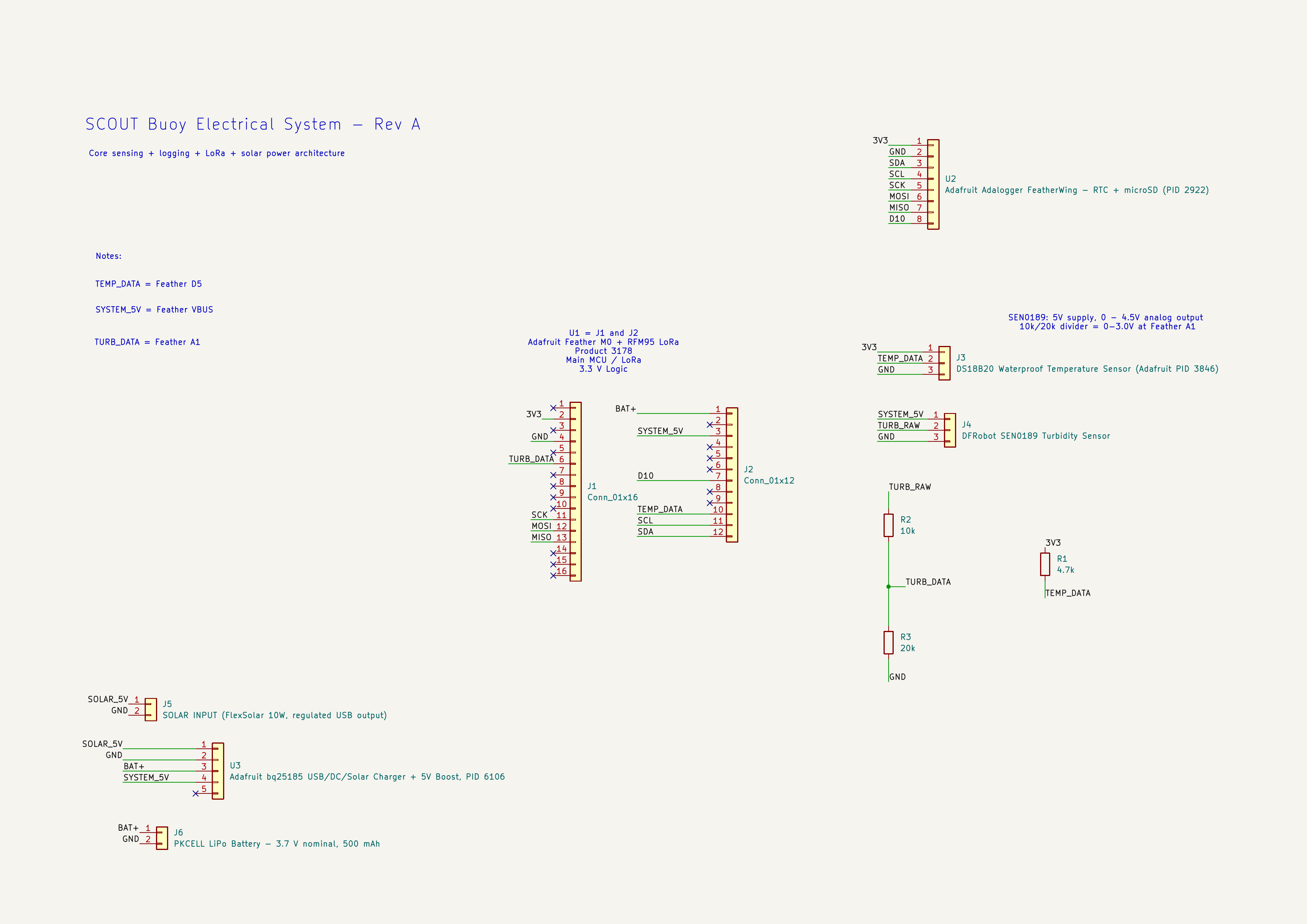
The current Rev A schematic — the project's first full electrical baseline — is ERC-clean and has undergone pre-hardware schematic and integration verification against manufacturer documentation. Physical assembly and bench validation are the next step.
- Microcontroller
- Adafruit Feather M0 (SAMD21)
- Radio
- RFM95 LoRa · RadioHead RH_RF95 · 915 MHz
- Clock
- PCF8523 RTC (wake alarm + timestamps)
- Storage
- microSD via Adalogger FeatherWing
- Power
- Rev A prototype: 1S LiPo through an Adafruit PID 6106 charger/boost board, regulated 5 V system rail. Longer-term deployment battery architecture remains under evaluation (ADR-0002)
- Temperature
- DS18B20 digital thermometer (±0.5 °C)
- Turbidity
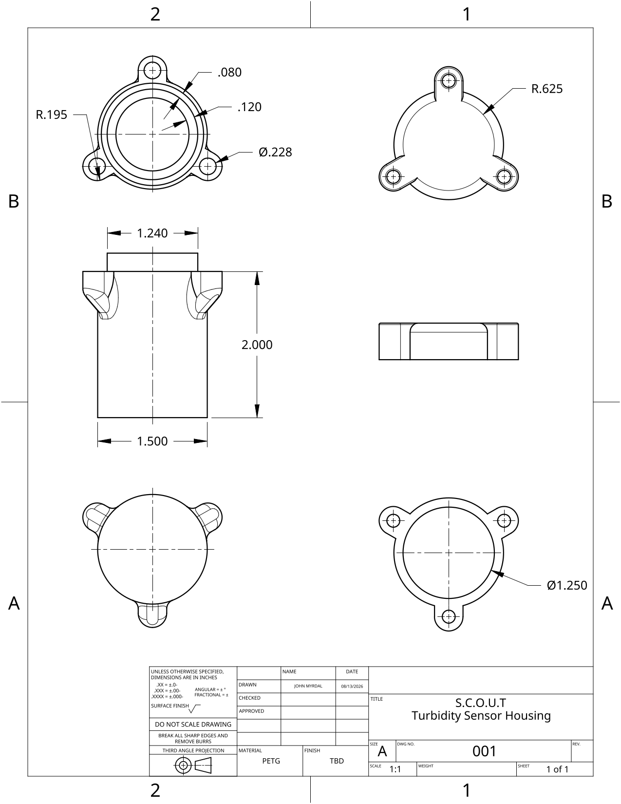
- Seeed Grove 101020752 optical transmittance sensor at 3.3 V, wired straight to the ADC — bench validation pending
- Acoustic
- Planned for a later electrical revision; hydrophone/interface selection under review
- Enclosure
- 3D-printed flange housing, large O-ring seal, 4.4 in bore
- Future PCB
- ESP32-C3 + SX1262
- Decision
- ADR-0001, accepted 2026-08-14
Electrical design
Rev A electrical schematic
SCOUT's Rev A electrical prototype establishes the controller/radio, power, temperature, turbidity and logging architecture. The schematic is ERC-clean and has undergone pre-hardware schematic and integration verification against manufacturer documentation — physical assembly and bench validation are the next step. Click to view full resolution.
The packet
44 bytes, three times a day
The binding constraint on a LoRa link is bandwidth. The buoy stores full data locally and transmits only its latest compact reading, three times a day, rather than raw waveforms. The packet layout is a versioned contract: the firmware encoder and the shore decoder are byte-identical, checked by a cross-language test so the two can never silently drift apart.
Raw audio is never transmitted. There is not enough LoRa bandwidth for waveform data, so the buoy stores audio on board and sends a 14-byte summary of each recording in the 44-byte packet. This is a settled design decision.
- Packet size
- 44 bytes (140-byte ceiling)
- Cadence
- 3 fixed slots / day: 00:10, 08:10 and 16:10 UTC
- Sampling
- 1 record / 30 min (48 / day)
- Carries
- The latest temperature, turbidity & battery reading
- Integrity
- Counter + CRC; malformed frames dropped
- Schema
- Versioned; byte-identical buoy ↔ shore codec
The shore link
LoRa to a base station on shore
The buoy talks to an ESP32-S3 base station on shore over a 915 MHz LoRa link. LoRa is built for exactly this: tiny payloads, long range, very low power.
Over seawater, the water itself is not the problem. Field studies of LoRa over open seawater have measured clear line-of-sight links out to tens of kilometres, and conclude the sea surface does not limit the link. The real constraint for S.C.O.U.T. is antenna height: the buoy's antenna sits only centimetres above the waterline, and near-surface links lose margin as the antenna drops toward the water.
So the roughly 2 km target is deliberately conservative. The plan is to raise the shore antenna to recover the link budget the low buoy antenna cannot provide, and to measure real over-saltwater range in the Phase 4 range test rather than trust a datasheet line-of-sight figure. The evidence for both bounds is in the references below.
On shore
What happens on shore
- Receive
- An ESP32-S3 base station listens for the buoy's LoRa packets
- Forward
- It pushes each packet over WiFi toward the dashboard
- Validate
- Check the counter and CRC; drop malformed frames
- Analyse
- Run the standard-library telemetry pipeline
- Publish
- Regenerate and push this static site
- Range target
- ~2 km line of sight (conservative)
Mechanical
Sealed above, sensing below
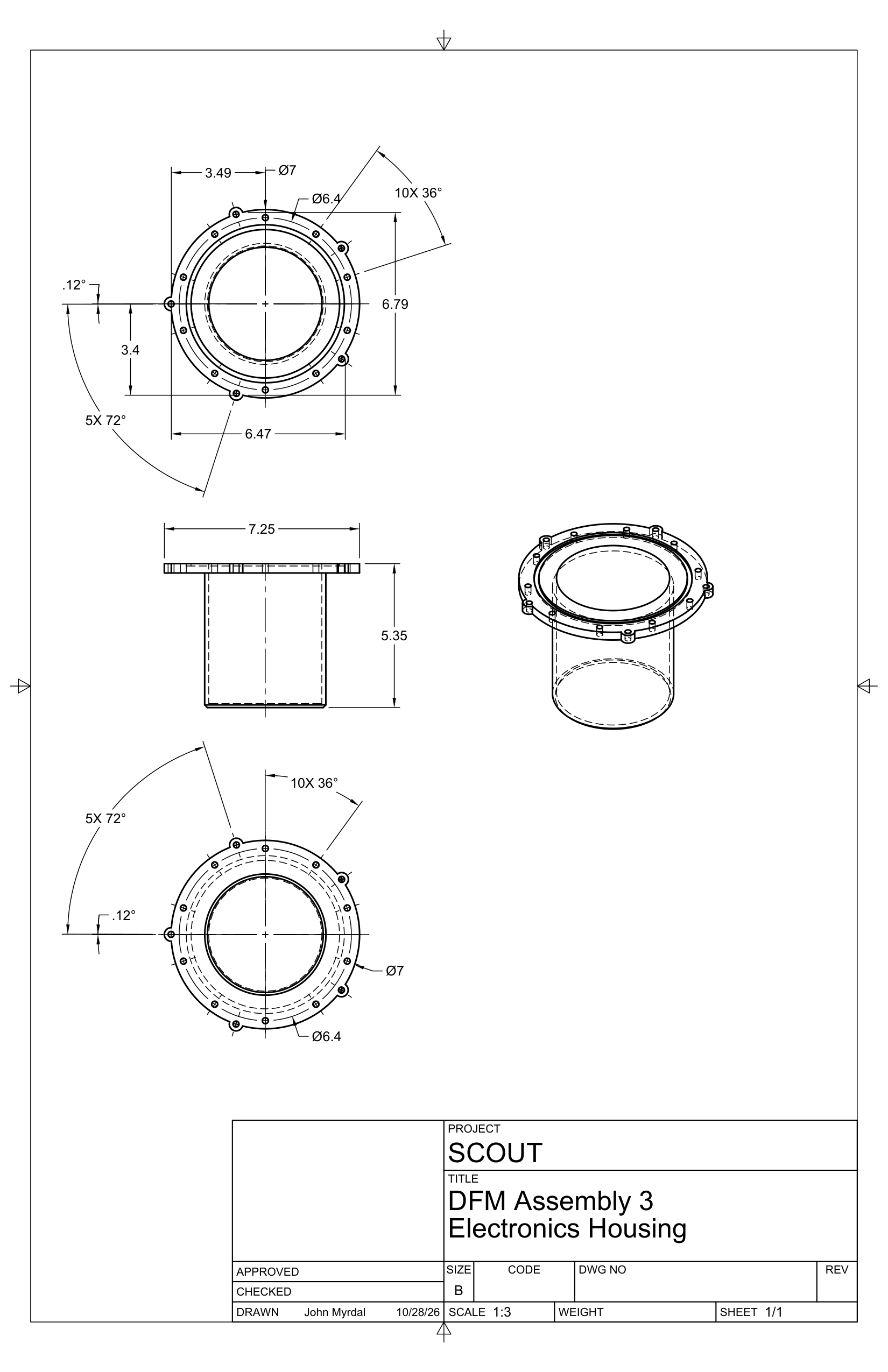
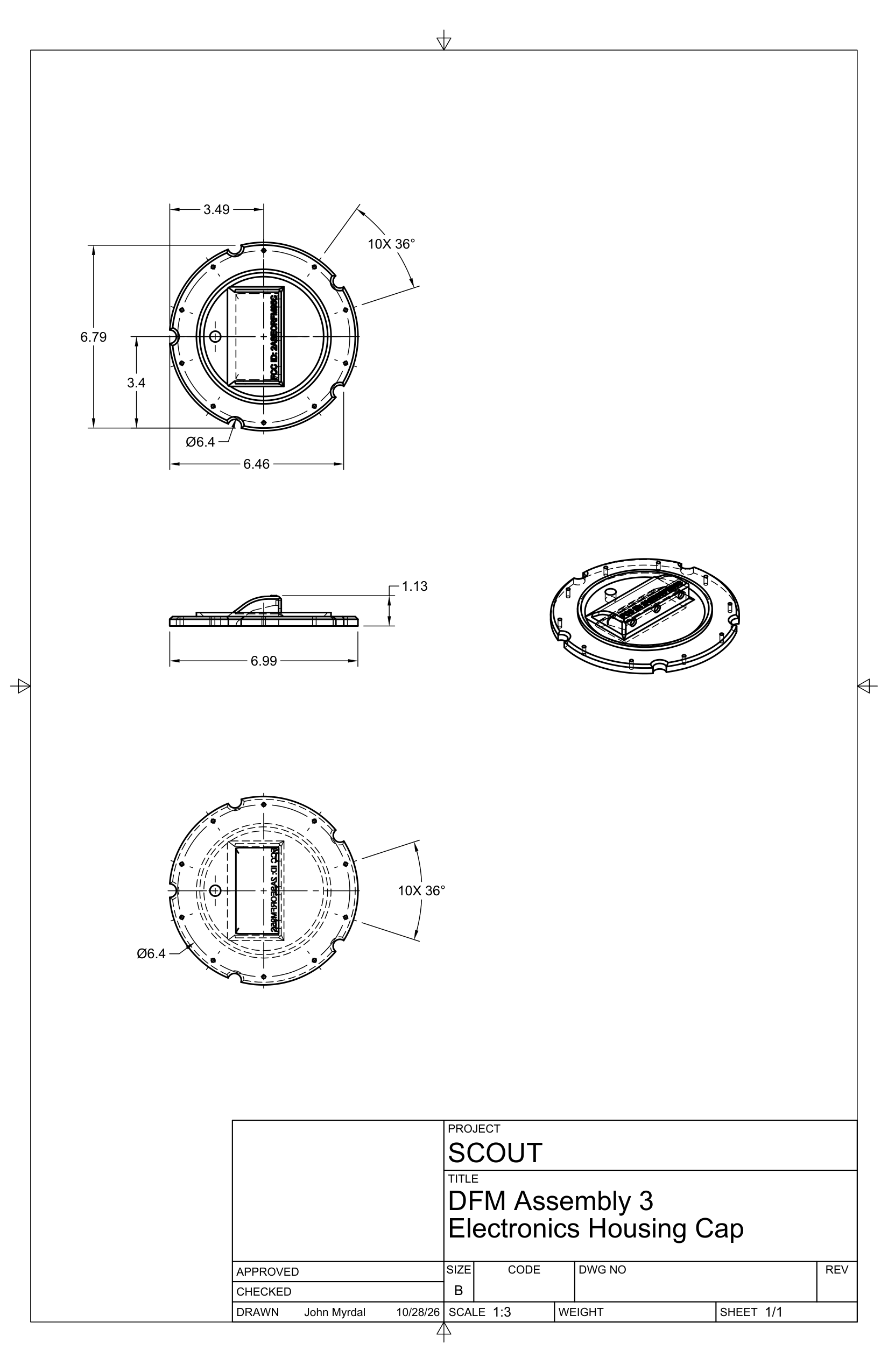
The electronics stay dry in a sealed housing above the waterline: a 3D-printed flange housing (4.4 in bore, 5 in tall) closed by a bolted lid and sealed with a large off-the-shelf O-ring, with cable glands in the lid. It sits in a printed float that holds it upright at the waterline, with the antenna above and the mooring attached to the float.
Below the housing, S.C.O.U.T. uses one sensor of each type at a single point rather than a multi-depth string (ADR-0003); the extra units on the bill of materials are field spares. The mooring is fixed and reef-safe, chosen to hold station with minimal disturbance to what it is measuring.
Mechanical design
The printed parts
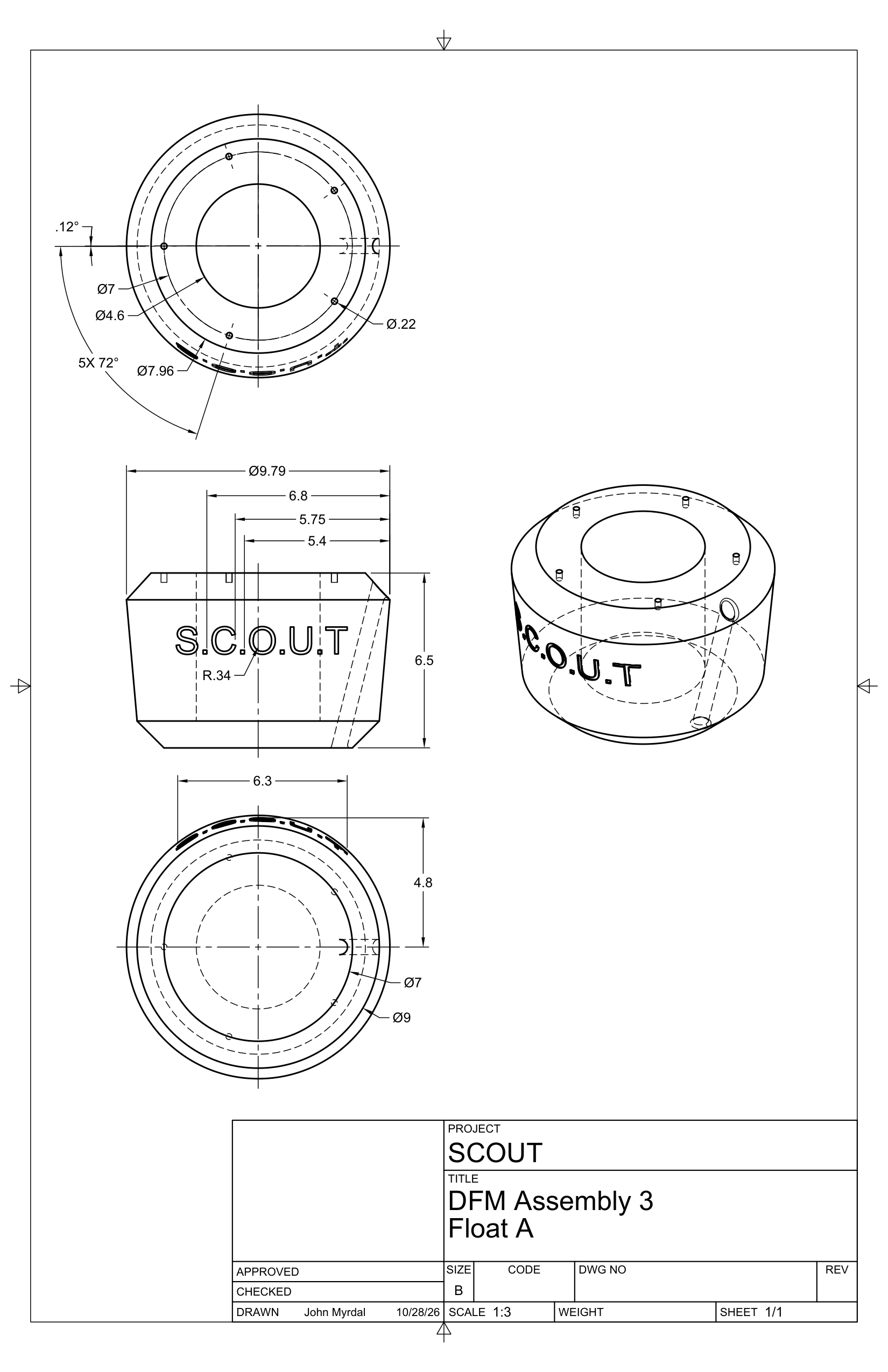
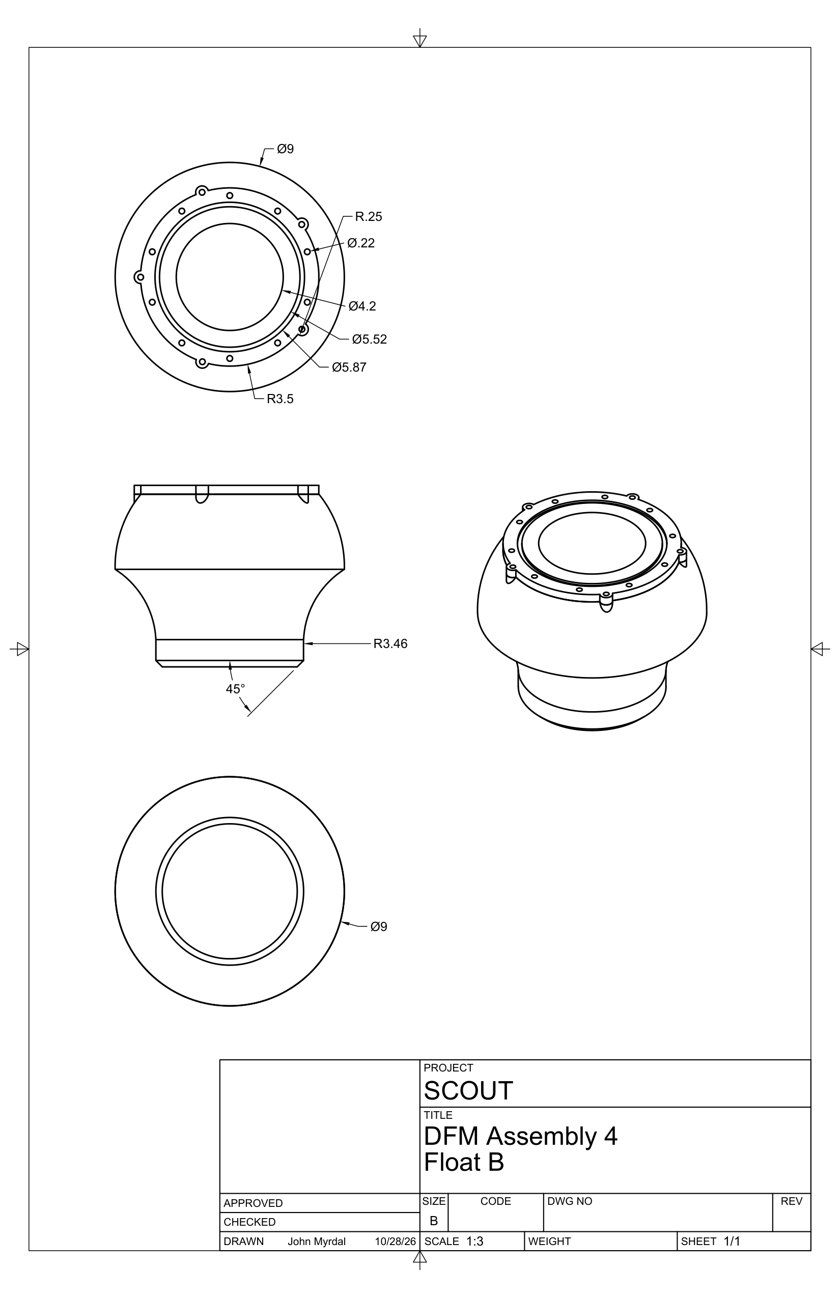
John Ryan Myrdal's CAD for the two printed floats, the electronics housing and its cap, and the turbidity-sensor housing, printed in PETG. Each drawing links to its full sheet.
Mechanical design
Will it stay upright?
Battery, electronics and antenna sit above the waterline, so a buoy is top-heavy by nature. We float every design in software before printing it.
Pick a design
Slide through the fifteen we have modelled, oldest to newest.
Change the weight
Make the electronics housing heavier or lighter.
Read the verdict
Green means it rights itself. The numbers behind it are underneath.
Each design’s real CAD is filled with water in 3 mm cubes. The waterline is where the water it displaces weighs as much as the buoy; then it is tilted in 5° steps to see which way the lift pushes. Checked against a plain cylinder, it matches draft and stiffness to about 1%.
What it does not tell us yet
Part masses for the concept designs are estimated from CAD volume, not weighed. Only printed and weighed parts (the bolted-wedge parts and the mushroom float) use measured weights, so trust those results most. The model is still water only: no waves, wind or mooring pull. Every estimate is listed in the simulator’s README.
References
Where these choices are grounded
The communications design leans on published LoRa-over-water propagation studies; the rest is specified in the project's own engineering records.
Communications over water
- Jovalekić, N., Drndarević, V., Pietrosemoli, E., Darby, I. & Zennaro, M. (2018). Experimental Study of LoRa Transmission over Seawater. Sensors 18(9), 2853. doi.org/10.3390/s18092853
- Gutiérrez-Gómez, A. et al. (2021). A Propagation Study of LoRa P2P Links for IoT Applications: The Case of Near-Surface Measurements over Semitropical Rivers. Sensors 21(20), 6872. doi.org/10.3390/s21206872
